

Exploding bandwidth demand, paired with limited pathway, conduit, rack, and switch-panel space, presents a serious conundrum for modern networks. Across high-performance computing (HPC) clusters, hyperscale data center interconnects (DCI), metro and mobile access networks, and long-haul links, operators struggle to expand capacity where physical space and cable weight are heavily constrained.
Rather than the high cost of expanding data center footprints or trenching new conduit, the industry is turning to multi-core fiber (MCF). This viable and commercially available space-division multiplexing (SDM) technology packs significantly more density into an optical fiber.
What is multi-core fiber (MCF)?
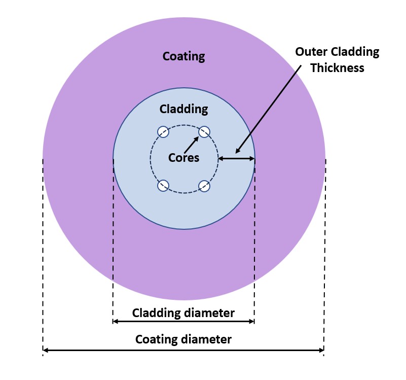
MCF differs from conventional fiber by incorporating multiple signal-transmitting cores within a single cladding structure rather than a single central core. MCF designs vary across several key dimensions:
- Core layout and count: Cores can range from 2 to 19 or more, arranged linearly, hexagonally, in a square, or in a circle.
- Core type: Cores can be single-mode, with typical 9 µm cores supporting one guided propagation mode, or few-mode, with larger cores supporting a small, deliberate number of spatial modes (typically up to 10) that each function as an independent data channel.
- Cladding dimensions: Outer cladding thickness (distance between the cladding edge and the center of the outermost core) varies with core count and layout. While overall cladding diameter can range from 125 to 250 microns (µm), maintaining the standard 125 µm diameter preserves compatibility with existing optical connectivity.
- Coating diameter: Primary acrylic coatings can retain the standard 250 µm diameter or reduce to 200, 190, or even 180 µm to maximize density and minimize weight.
Manufacturers must carefully balance these variables to optimize density, optical performance, and mechanical robustness, while ensuring practical compatibility with existing fiber technology.
Weakly vs. randomly coupled MCF
MCF designs fall into two primary categories:
- Weakly coupled MCF: Each core is isolated from adjacent cores and operates as an independent channel. This requires a relatively large core pitch (spacing between cores) and refractive-index engineering to suppress inter-core crosstalk. While a larger cladding diameter can reduce crosstalk, maintaining a standard 125 µm cladding preserves compatibility with existing connectorization. However, this typically limits core count to 8 or fewer. Differential gain among cores accumulates linearly over distance in a weakly coupled MCF, which can degrade long-haul signal quality. It is therefore ideal for short-to-medium reaches, including HPC clusters, DCIs, and metro/mobile access networks. To integrate with existing single-mode networks, weakly coupled MCF requires fan-in/fan-out (FIFO) devices to split or combine individual signals into and out of each distinct MCF core.
- Randomly coupled MCF: Cores are placed much closer together, significantly tightening core pitch to achieve higher density. This deliberately introduces random mode coupling, distributing optical energy among the cores. In addition to requiring FIFO devices, randomly coupled MCF also necessitates advanced multiple-input, multiple-output digital signal processing (MIMO-DSP) at the receiver to demodulate the mixed signals. Intentional random coupling mitigates modal dispersion, mode-dependent loss, and nonlinear impairments, simplifying MIMO-DSP calculation complexity. However, core pitch must be precisely controlled; if cores are too close, strong mode coupling can increase the travel-time differences between modes. Randomly coupled MCF is better suited for long-haul transoceanic and transcontinental links.
Key Engineering and Implementation Considerations
While maximizing density is the primary goal, it cannot come at the expense of optical performance, mechanical reliability, or ecosystem compatibility.
- Compatibility with existing infrastructure: For MCF to succeed commercially, it must integrate seamlessly with existing installation practices, fabrication processes, and connectorization. Maintaining a standard 125 µm cladding diameter limits core density but is essential for leveraging conventional ferrule technology and standard fusion-splicing equipment.
- Balancing density against performance: Squeezing more cores into a single cladding tightens core pitch, increasing inter-core crosstalk. It also reduces cladding thickness, which increases attenuation. For few-mode cores, engineers must also minimize differential mode delay (DMD), the difference in travel time between the fastest and slowest modes. Like standard multimode fiber, this is typically achieved via a graded refractive index profile.
- Mechanical protection vs. space savings: Reducing coatings below 200 µm yields compact, lightweight cables but sacrifices structural cushioning. These thinner coatings leave fibers more vulnerable to microbending losses and environmental stress, demanding advanced cable designs and careful handling.
- Operational risk and restoration: Network architects must balance pathway and cable density gains against practical day 2 operational realities. Packing multiple data streams into a single strand concentrates shared failure exposure — a single fiber break or damage event impacts several channels simultaneously. To mitigate this risk, operators must plan for robust spare capacity and route diversity. Network designers must also address restoration complexity. FIFO breakout assemblies must be readily accessible for rapid inspection, troubleshooting, repair, or replacement.
- Testing and measurement: Achieving performance parity with existing single-mode fiber requires standardized, repeatable testing methodologies, parameters, and record-keeping frameworks. Manufacturers and operators need precise benchmarks for inter-core crosstalk, insertion loss, attenuation, return loss, and core alignment and mapping.
Commercial Deployment and Industry Outlook
Ultimately, MCF success hinges on each core’s usability. Squeezing more channels into a shared cladding offers little value if each channel cannot be just as reliably connectable, identifiable, testable, and maintainable as a traditional single-mode fiber.
Compatibility factors explain why weakly coupled MCF currently leads commercial adoption. Weakly coupled MCF interfaces with existing transceivers via FIFO interfaces, while standard 125 µm cladding aligns with conventional ferrule technology. In contrast, randomly coupled MCF requires next-generation MIMO-DSP chipsets, non-standard manufacturing processes, and significant R&D investment that the industry is unlikely to justify until bandwidth demand completely outgrows the limits of weakly coupled MCF.
With MCF already commercially deployed, this technology is poised to significantly impact TIA TR-42, the engineering committee responsible for developing cabling infrastructure standards. In an upcoming blog, we’ll explore this impact and the need to define clear roles, avoid overlap, and align with international standards.